 Quick Navigation
 All projects
  Hardware
 Links
Links Top projects
Alan numitron clock
Clapclap 2313/1386
SNES Pi Webserver
USB Volume/USB toys
Smokey amp
Laser cutter
WordClock
ardReveil v3
SNES Arcade cabinet
Game boy projects
cameleon
Home Presence Detector
 GitHub
AlanFromJapan
 Contact me
 Who's Alan?
Akizukidenshi
Elec-lab
Rand Nerd Tut
EEVblog
SpritesMods
AvrFreaks
Gameboy Dev
FLOZz' blog
Switch-science
Sparkfun
Suzusho
Datasheet Lib
Reddit Elec
Ermicro
Carnet du maker (fr)
rapideusb
Last update: Sat Jan 10 23:04:54 2026
How to use this? USB without ArduinoAlternate version for SNES joypad adapter: SNES pad USB adapter
Alternate version for ATtiny2313 and better with some fixed RapideUSBII
Summary
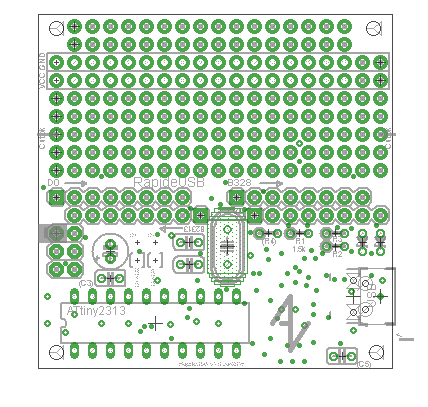
 A one afternoon work to make this board. Goal: make the V-USB project simple , with a board that already has everything you need. Populate it, burn the program and you're good to go! Works for ATtiny2313 DIP or ATmega328 (all the ATmegaxx8 family in fact) in SMD package.
This board is made to make your life easier if:
- You go with the Zener diodes approach: your mCU runs on 5v, life is easy. For the small downsides see V-USB hardware documentation.
- You plan to use pins D2 and D4 for your connectivity. You can use other pins though, you'll have to not solder the jumpers and wire D+/D- to the pins you want
- You plan to use ATtiny 2313 DIP or ATmegaxx8 SMD family
I know the board is tight and some solderings might require a little attention but unless you have Parkinson disease (wish you not, terrible stuff) or solder with a blowtorch, that should be fine. Just be a little careful.
If you have suggestions about how to improve the layout, please let me hear.
Self-criticizing and possible improvements
- [High] Add holes for D+/D- to plug a USB cable directly instead of a micro/mini plug
- [High] OTG connection as a client? Maybe with a solder jump or allow to solder these special connectors? (ie: to be able to connect a smartphone)
- [Medium] Make those lines that carry power (VCC & GND) bigger, it's just signal size now, no way it can draw more than a few tens of mA)
- [Medium] Put a solder mask on the bottom for the power rail! Hard to figure where is gnd/vcc...
- [low] Add a V-USB logo
- [low] The power rail have solder mask on top (bottom is ok)... how did I do this miracle? Replace with regular ones
- [low] Provision for external power + USB connection, like a self powered hub or allow the connected smartphone to connect and charge
Schematics
On GitHub : https://github.com/AlanFromJapan/alanarduinotools/tree/master/eagle/RapideUSBREADME ! Things to know
- The board has 2 solder jumpers labelled D+=D2 and D-=D4: if you use D2 (as D+) and D4 (as D-) as default, just solder close these jumpers. If not, let them open and join the solder pad to the pin you're using.
- Corollary: if you don't solder these pads but use my default pins, nothing will work.
- PORT D is common to both mCU, PORT C is only available for ATmega328 and PORT B is implemented separately. Reason is that the ISP wiring on both mCU go to PORT B but the pins are different: MISO is PB6 on the tiny and PB4 on the mega. It would result in a big mess shorting pins. I could have put solder jumpers but I had space so...
- For all the ports the pin 0 is the square 口 pad. Count up from there, farthest is number 7.
- Board is a default 5cm x 5cm
- You can cut the board at the level of the 3rd free row (where there's the "cut ok" top silk message). You board will become a 5cm x 3.3cm in case you need space.
Setting the fuses
Fuses setup for a ATtiny2313
Fuses for ATtiny2313:
# Set the fuses
avrdude -pt2313 -cavrispmkII -u  -Ulfuse:w:0xce:m -Uhfuse:w:0xdf:m -Uefuse:w:0xff:m

Fuses setup for a ATmega8a
BOM
| Mandatory |
Part |
Value |
Device |
Package |
| x |
C1 |
22pF |
C-EU025-024X044 |
C025-024X044 |
| x |
C2 |
22pF |
C-EU025-024X044 |
C025-024X044 |
| C3 |
1uF |
C-EU025-024X044 |
C025-024X044 |
|
| x |
C4 |
10uF+ |
CPOL-EUE2-5 |
E2-5 |
| C5 |
1uF |
C-EU025-024X044 |
C025-024X044 |
|
| x |
R1 |
1.5k |
R-EU_0204/2V |
0204V |
| x |
R2 |
68 |
R-EU_0204/2V |
0204V |
| x |
R3 |
68 |
R-EU_0204/2V |
0204V |
| R4 |
1M |
R-EU_0204/2V |
0204V |
|
| ! |
UC1 |
ATtiny2313 or AT90S2313P |
AT90S2313P |
DIL20 |
| ! |
UC2 |
ATMEGAxx8P |
ATMEGA328_SMT |
TQFP32-08 |
| !! |
USB_MICRO |
USB_MICROB_PLUGCONN-11752 |
USB_MICROB_PLUGCONN-11752 |
USB-B-MICRO-SMD_V03 |
| !! |
USB_MINI |
USBSMD |
USBSMD |
USB-MINIB |
| x |
Y1 |
12-20MHz |
CRYSTALHC49UV |
HC49U-V |
| x |
ZENER1 |
3.6v |
ZENER-DIODEZD-2.5 |
ZDIO-2.5 |
| x |
ZENER2 |
3.6v |
ZENER-DIODEZD-2.5 |
ZDIO-2.5 |
!: use an ATtiny2313 or an ATmega328 (SMD version) not both
!!: USB micro or mini connector are on top of each other so pick one
C3/C5: 1uF caps to put the closest to the mCU, not mandatory but encouraged
R4: some people put a 1Mohm pullup, some don't. Not mandatory.
Code
The Eagle schematics are on GitHub as usual. Look into my other USB gadgets projects : Tricolor USB alert (ATtiny2313) or Finger Password Keyboard (ATmega328).Pictures

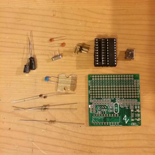
See the BOM for details. Took 25 minutes to assemble, no big issue.

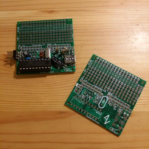
2313 version assembled. Just be careful next to the USB connector with the diodes and resistor, space is tight, you might want to place them wisely (see the 3 vertical resistors next to USB connector)
electrogeek.tokyo ~ Formerly known as Kalshagar.wikispaces.com and electrogeek.cc (AlanFromJapan [2009 - 2026])