 Quick Navigation
 All projects
  Hardware
 Links
Links Top projects
Alan numitron clock
Clapclap 2313/1386
SNES Pi Webserver
USB Volume/USB toys
Smokey amp
Laser cutter
WordClock
ardReveil v3
SNES Arcade cabinet
Game boy projects
cameleon
Home Presence Detector
 GitHub
AlanFromJapan
 Contact me
 Who's Alan?
Akizukidenshi
Elec-lab
Rand Nerd Tut
EEVblog
SpritesMods
AvrFreaks
Gameboy Dev
FLOZz' blog
Switch-science
Sparkfun
Suzusho
Datasheet Lib
Reddit Elec
Ermicro
Carnet du maker (fr)
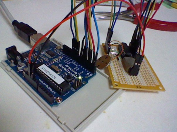
Arduino and a YMZ294
Last update: Tue Feb 17 20:52:01 2026
Tadaaaaa ♪

volume is low, you can see me in reflection ... I know ... hope you like it anyway.
See also how to generate tunes from MIDI files at MIDI, CSharp and Yamaha chips.
Documentation
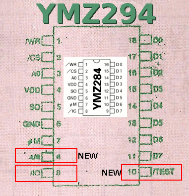
Suggested wiring hint here under. The bold pins are the difference between the YMZ294 and the YMZ284. You can wire it otherwise, but if you wire like that my samples will work directly :| "Left side" |
"Right side" |
|
|
Things to know
- Beware of short-circuits : the oscillator I got had its case connected to the ground, and one Vcc wire too long was short-circuiting because touching it.
- You need 11 pins to drive it : 8 for data bus, 3 for control (WR, CS, A0)
- Port TEST should be left un-connected
- Port IC (reset) can also be left unconnected (it seems at least)
Note about the oscillator
Since many people asked me, you must use here an oscillator, and not a crystal. Reason is that you must feed your chip with a square signal on just one pin, so no crystal here (unlike what you would have next to your Atmel MCU). Anything that makes a square signal will do the trick, but must be in range 1MHz to 8Mhz.
Documentation
Datasheets
NONE on the net, not even on Yamaha website.So, by reading the japanese documentation provided by Akizuki, I got it is the same as a YMZ284 (YMZ294 has 2 extra pins, one for test mode and the other one for choosing the crystal frequency 4/8 MHz). Wiring is the same as YMZ284 therefore.
And to me it looks like also its friend the YM2149. So I put these documentations here :
- ymz284.pdf <- you want this one (in english)
- ym2149.pdf <- FYI (in english)
- ymz294.pdf <- original documentation from Akizukidenshi (in Japanese)
Websites and tutorials
- Wikipedia : no datasheet but you've got an idea of what it does : http://en.wikipedia.org/wiki/General_Instrument_AY-3-8910
- YMZ294で楽しむPSG音源 http://hijiri3.s65.xrea.com/sorekore/develop/pic/PIC04_YMZ.htm (cabling details)
- http://homepage2.nifty.com/sampodo/craft/psg.html
- Arduino%20YMZ294で音をならしてみる http://d.hatena.ne.jp/kazuya_a/20090625/1245926938 (sample code working 100% fine!)
- http://web.mac.com/kuwatay/morecat_lab./USB-PSG.html
- This guy is a genius http://www.linusakesson.net/hardware/chiptune.php
- Wow a PSG shield ! Nice! http://shield.io/psg
- Hey some guy used my stuff : happy (^。^)v http://blog.goo.ne.jp/jj1wkn/e/9b90832d25e8c5651572dd3ebbcceea8
Midi music
- Final Fantasy
- Super mario
Code
- My "library", just a .h file with all you need to pilot it, and a sample program on my GitHub.
- Wire it and you get Final Fantasy IV music !
- Other inspirations and precious help : YMZ294_Test.pde Directly taken from the link here above , no change at all and worked just fine.

Shopping
- ヤマハ音源IC(YMZ294)(includes a 4MHz oscillator) for 500 ¥ http://akizukidenshi.com/catalog/g/gI-00181/
electrogeek.tokyo ~ Formerly known as Kalshagar.wikispaces.com and electrogeek.cc (AlanFromJapan [2009 - 2026])