 Quick Navigation
 All projects
  Hardware
 Links
Links Top projects
Alan numitron clock
Clapclap 2313/1386
SNES Pi Webserver
USB Volume/USB toys
Smokey amp
Laser cutter
WordClock
ardReveil v3
SNES Arcade cabinet
Game boy projects
cameleon
Home Presence Detector
 GitHub
AlanFromJapan
 Contact me
 Who's Alan?
Akizukidenshi
Elec-lab
Rand Nerd Tut
EEVblog
SpritesMods
AvrFreaks
Gameboy Dev
FLOZz' blog
Switch-science
Sparkfun
Suzusho
Datasheet Lib
Reddit Elec
Ermicro
Carnet du maker (fr)
rapide7seg
Last update: Sat Jan 10 23:04:54 2026
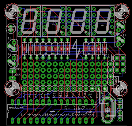
 A small 5x5cm board to quickly use up to 4 small sized 7 segments. They are for sell for 150 JPY a pack of ten at Japan's top shop Akizuki Denshi : http://akizukidenshi.com/catalog/g/gI-01492/
Some points of interrests :
- Works with a footprint for a ATmegaxxx8 family, with an ISP and crystal and power rail cap
- There's 4 x 7segs, common anode, and it's planned to work with POV (you can light just one at a time)
- The 7segs (+1 dot) 8 segments are driven by the PORTC entirely, PORTD controlls which 7seg you talk to.
- There's room for through holes resistors (one for each pin) that can be replaced by a wire or a solder pad, same for the control resistors
- The 7 segs CAN be driven by a NPN transistor (in case you want a nice, stable, not related to the number of leds used luminosity)
- Use this if you want bright reading even in daylight : 1 NPN transistor per 7 seg, 1 resistor to command the NPN transistor and 7 resistor to limit current
- The 7 segs CAN be driven direclty from the uC which requires less components BUT means you short the B-E of the transistor (there's a line on the board) .
- The luminosity of the 7segs will vary according the number of segments ligthened : since current is constant and provided by the uC and you should cap it to 20-30 mA, you will have bright 1's (2 segments) and pale 8's (7 segments so 20mA /7 = 3 mA per led). Just 1 resistor per 7seg.
 As usual, there are some things to fix:
- Only one error but quite annoying : when I made the solder pins fields I used vias instead of the sparkfun pins... bad idea, the vias have their border covered with the resin, can't be easily soldered. You can still access the pins of the ATmega, but can't use that little space in from of it to solder other few components. Quite annoying, you have to make some wires to some other board or "air wire" the components on the other side of the board. Works but uncool...
- 20240419: more than 10 years later I plan to use this board for the 3rd time and notice that I used NPN transistors to SOURCE current... which is BAD. It will work for that little current (it did the first time I used it) but it's a design fault, they should have been PNP. I guess I made some progress in 10 years luckily (facepalm 🤦).
electrogeek.tokyo ~ Formerly known as Kalshagar.wikispaces.com and electrogeek.cc (AlanFromJapan [2009 - 2026])