 Quick Navigation
 All projects
  Hardware
 Links
Links Top projects
Alan numitron clock
Clapclap 2313/1386
SNES Pi Webserver
USB Volume/USB toys
Smokey amp
Laser cutter
WordClock
ardReveil v3
SNES Arcade cabinet
Game boy projects
cameleon
Home Presence Detector
 GitHub
AlanFromJapan
 Contact me
 Who's Alan?
Akizukidenshi
Elec-lab
Rand Nerd Tut
EEVblog
SpritesMods
AvrFreaks
Gameboy Dev
FLOZz' blog
Switch-science
Sparkfun
Suzusho
Datasheet Lib
Reddit Elec
Ermicro
Carnet du maker (fr)
Fixing a gameboy
Last update: Tue Feb 17 20:52:02 2026
Why fixing a gameboy
Recently I went to Super Potato http://www.superpotato.com/ and bought a original Gameboy for 300 JPY (roughly 2.5 euro) marked as junk. It means wether it works or not, they don't care (most likely something is awry).Well, mine has a few issues:
- A few dead columns on the left hand (let say 3-4)
- Screen protector lid fell
- Dirty
How to fix dead columns
Seems it can be fixed by applying pressure or quick reflow on the connector. Tried, works PERFECTLY.Basically,
- Open up, get access to the screen, put some battery at the back or wallwart, you must do this with power ON
- Remove the black rubber sticker over the screen connector, just at the bottom of the screen. Be nice and don't rip off the connector itself.
- Apply heat with a 30w iron. Don't worry for the brown connector, it won't melt, it's kapton. Don't try to burn it neither. Use moderate strength, but use it.
- While heating, check for the other columns that will go blinking. In my case at first everything seemed worse, but when cooling and remounting, it all went fine.
It just works fine (do it with gameboy on to check the result). It's quite scarry because while doing it lots of other columns seem to die too and looks like a fool's job, but no worries, in the end you have your gameboy back (with a bit of luck). See the pointers here under for operation details, all credits go to them.
Documentation is here :
- http://8bc.org/forums/viewtopic.php?id=5679&p=1
- http://wiki.answers.com/Q/How_do_you_fix_invincible_lines_on_original_game_boy_screen
- Hall of fame http://hackaday.com/2011/04/10/hackaday-links-april-10-2011/
 |
 |
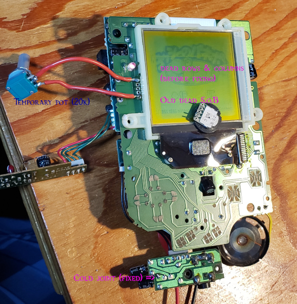
| Before : you can clearly see vertical dead pixel columns on the left. The rubber is already removed, apply heat and moderate strength on the left side. |
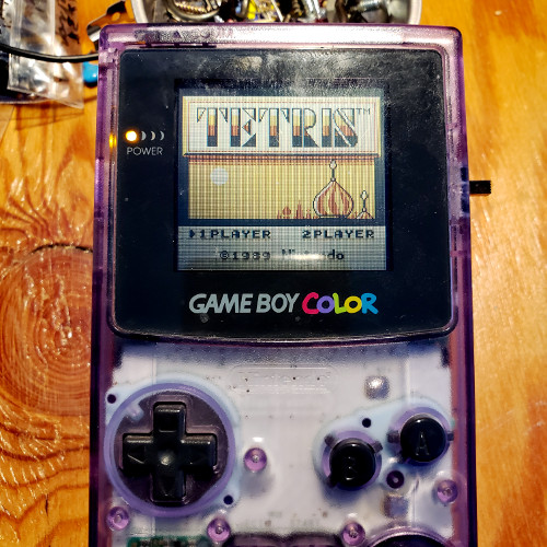
After: perfect! When I finished the heat-resolder part, 2 columns were still dead, but after mounting everything back (and don't ask me why), everything is as brand new (^_~)b |
Fix the screen lid
Remove the remaining glue (acetone and/or sandpaper), but don't overdo it like me or the gray border will vanish (T_T) I will have to polish it and remove completely to fix my mistake.
When unpolishing the screen, stick it to the table with nylon tape so you can work safe, and sand-paper it.
Clean it up
Open the gameboy, take the cover to the sink and brush ! Soap and sponge, acetone and toothbrush, you can get something quite ok as a result.Change the led color
Low voltage forward leds : red, green, blue
Veeeery easy, you just replace the led to the condition that your led will shine with 2.7v :- Open the gameboy
- locate the front pcb with the screen
- Unsolder the through-hole red led. I just used some copper solder wick, remove the solder, remove the led
- Put a 3mm led instead (blue for me) and care for the polarity
- You might need a resistor to limit the current though the led. I didn't measure it, but led made lots of progress of the last 20 years in terms of efficiency and my blue led is waaaay too bright, you can't look the screen in front. A small resistor or depolishing the led with sandpaper might do the trick. Maybe both. (edit: my option was the depolishing with sandpaper and it works very nicely)
- Cut the legs and reassemble : tadaaa♪ you have your custom gameboy
Higher voltage forward : white
You will have to add an additional step to the end of the here above procedure : you need to augment the voltage by diminishing the value of the led resistor (labelled R8 on a gameboy pocket). By the way gameboy is a 5v device, there's a buck booster inside.By default value is 46 kOhm (which is a lot) and cause a red led (lowest voltage forward) to shine ok (specially seen from front) but will cause your white led to barely light up.
Two options :
- The hard way : replace the led with another SMD led. Careful it's extra small, you need a sure hand to solder it : hard but doable. As I said, name is R8 on a gameboy pocket and value is 46 kOhm => label says "463"
- The easy way : hey, you noticed that just above and just under that resistor there are 2 vias? And did you noticed that they have just the width of a 1/4 watt resistor leg? Well I did. Stick the led in those holes, solder the vias (there's a small border, it's doable, no worries) and you have just made a nice parallel resistor !
- Explanation : 2 resistor in parallel become a resistor with value R = (R1 x R2) / (R1 + R2). Hint : if you put a big resistor and a smaller resistor, the result will be around the smallest one value.
- My case : I tested on a breadboard with a potentiometer to find the approximate resistance I needed : about 3 kOhm give a dim yet nice brightness with my white led (remember it will be right in your face, don't make it too bright). I found a 2.4 kOhm resistor in my box, a little math says that R = (R1 x R2) / (R1 + R2) with R1 = 46,000 and R2 = 2,400 makes R = 2,280. Soldered, measured : results are according theory for once! Works nicely, maybe a little dim but better that then too bright, no?

Surrounding R8 resistor, the 2 vias have just the right size to welcome a parallel resistor...

Pink led on a Silver Gameboy pocket. Not bad right? Used a 1.5kOhm resistor in parallel of R8 for this pink led that would not even light with default resistor.
Gameboy color power switch fix
One of my Gameboy color power switch gave up on me, so I just replaced it with what I had a hand, uglier and bigger. In case you need to know, you need to know, you need to switch the pins C and 3 (see pictures below).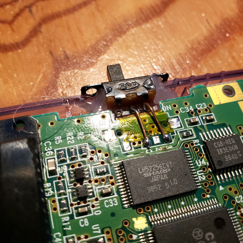
Gameboy DMG (the brick) fix (Jan 2024)
This is becoming a collection of fixes, it's a nice walk into memory to read this. So this time I got an originally dead DMG, an old lady [DMGLCD_02] model. Didn't took picture of all the issues (wasn't sure it was fixable and also forgot):Also fixed the dead pixels, could get nearly all the columns back, but not the half dead rows (can't always win).
electrogeek.tokyo ~ Formerly known as Kalshagar.wikispaces.com and electrogeek.cc (AlanFromJapan [2009 - 2026])