 Quick Navigation
 All projects
  Hardware
 Links
Links Top projects
Alan numitron clock
Clapclap 2313/1386
SNES Pi Webserver
USB Volume/USB toys
Smokey amp
Laser cutter
WordClock
ardReveil v3
SNES Arcade cabinet
Game boy projects
cameleon
Home Presence Detector
 GitHub
AlanFromJapan
 Contact me
 Who's Alan?
Akizukidenshi
Elec-lab
Rand Nerd Tut
EEVblog
SpritesMods
AvrFreaks
Gameboy Dev
FLOZz' blog
Switch-science
Sparkfun
Suzusho
Datasheet Lib
Reddit Elec
Ermicro
Carnet du maker (fr)
Clapclap
Last update: Sat Jan 10 23:04:53 2026
Basically an re-implementation of that http://www.instructables.com/id/How-to-make-a-Clap-Clap-on-Clap-Clap-Off-switch-/
Just a pretext to play with OpAmp and microphone...
See also the more recent version using Attiny 2313 : Clapclap 2313 or Attiny13 : Clapclap 1386

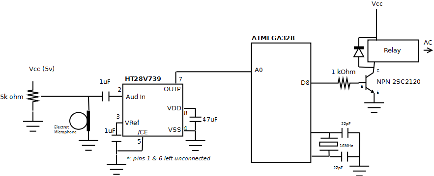
Schema : low quality sorry, I just had Dia under my hand...

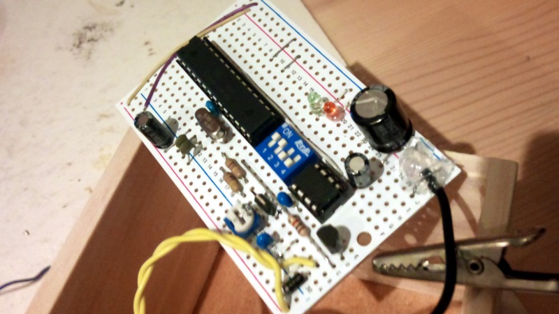
The board. Back to front the uC, on the left the quartz and capacitors, then a on board switch for debug led, the 8 pins amp and the transistor and diode going to the relay.

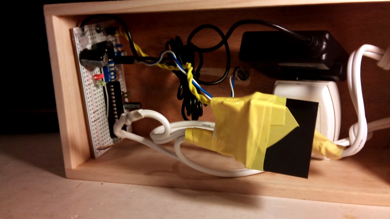
In the box ... (the black cube mommified in yellow tape is the relay, on the right is the cell phone charger used as power source)

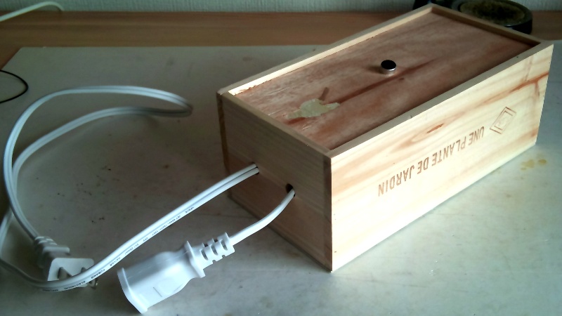
... and the box itself.
Just a pretext to play with OpAmp and microphone...
See also the more recent version using Attiny 2313 : Clapclap 2313 or Attiny13 : Clapclap 1386
Schema

Schema : low quality sorry, I just had Dia under my hand...
Components
- ATMEGA 328 : too big for that but only those available having an ADC.
- 0.1 uF anti ripple the closest possible to Vcc/GND pins
- Crystal 16 MHz and 2 capacitor 22pF
- HT82V739 HOLTEK audio amp, very nice to use, very few components
- 2x 1 uF capacitor (the one before the input is mandatory at least !)
- 47 uF anti-ripple capacitor
- Electret microphone
- 5kOhm variable resistance to tune the micro amplification and the sensitivity
- Power stuff like :
- 1 cheap cell phone charger (5v 750 mA 500 JPY at ドンキホッテ)
- A big cap anti-ripple 100 uF
- No regulator, the cell phone charger is already regulated it seems to 5.30 V
- Additional bling bling :
- leds and resistor for debuging
- Resistor and transistor NPN to drive the relay
- Relay [942H-2C-5DS] 5v 5A 125 V
- Internal resistor is 47 ohm so at 5v it draws about 100 mA (confirmed by measurement)
- 1 diode to avoid reverse current generated when relay turns off
Pictures

The board. Back to front the uC, on the left the quartz and capacitors, then a on board switch for debug led, the 8 pins amp and the transistor and diode going to the relay.

In the box ... (the black cube mommified in yellow tape is the relay, on the right is the cell phone charger used as power source)

... and the box itself.
Code
One can find that also on my google code account/* ardClapClap Clap twice, it triggers on/off a relay and whatever is plugged on. http://kalshagar.wikispaces.com/Clapclap This code is in the public domain. */ #define DEBUG #define LED_PIN_CLAP 6 #define LED_PIN_CLAPCLAP 7 #define RELAY_PIN 8 void setup() { #ifdef DEBUG Serial.begin(9600); #endif pinMode(LED_PIN_CLAPCLAP, OUTPUT); pinMode(LED_PIN_CLAP, OUTPUT); pinMode(RELAY_PIN, OUTPUT); } #define CLAP_THRESHOLD 600 #define CLAP_GAP_IN_MS 300 #define CLAP_GAP_TOLERANCE 65 #define CLAP_GAP_MIN (CLAP_GAP_IN_MS - CLAP_GAP_TOLERANCE) #define CLAP_GAP_MAX (CLAP_GAP_IN_MS %20 CLAP_GAP_TOLERANCE) unsigned long mLastClap; boolean mRelayStatus = false; void loop() { int sensorValue = analogRead(0); if (sensorValue > CLAP_THRESHOLD){ unsigned long vNow = 0; vNow = millis(); unsigned long vGap = vNow - mLastClap; #ifdef DEBUG Serial.print("clap ! mLastClap = "); Serial.print(mLastClap, DEC); Serial.print(" ; vNow = "); Serial.print(vNow, DEC); Serial.print(" ; vGap = "); Serial.println(vGap, DEC); #endif //blink "clap" digitalWrite (LED_PIN_CLAP, HIGH); delay(50); digitalWrite (LED_PIN_CLAP, LOW); if ( //initialized mLastClap != 0 //when overflow, last is after current, discard simply //and ensure that vGap is signed correctly && mLastClap < vNow //within range of duration and tolerance && vGap >= CLAP_GAP_MIN && vGap <= CLAP_GAP_MAX ){ //switch relay status mRelayStatus = !mRelayStatus; digitalWrite(RELAY_PIN, (mRelayStatus ? HIGH : LOW)); //blink "clap-clap" digitalWrite (LED_PIN_CLAPCLAP, HIGH); delay(500); digitalWrite (LED_PIN_CLAPCLAP, LOW); #ifdef DEBUG Serial.print("Calp-clap with delay of: "); Serial.println(abs(vNow - mLastClap), DEC); #endif //avoid triple clap to on-off stuffs, reset the last clap //would be better with a flag "triggered/dormant" but this will //do the trick in most the cases mLastClap = 0; } else { //store last time mLastClap = vNow; } } }
Links
- A simple explanation on how to plug a microphone http://www.dtic.upf.edu/~jlozano/interfaces/microphone.html
- Mind variable resistor before the microphone!
electrogeek.tokyo ~ Formerly known as Kalshagar.wikispaces.com and electrogeek.cc (AlanFromJapan [2009 - 2026])