 Quick Navigation
 All projects
  Hardware
 Links
Links Top projects
Alan numitron clock
Clapclap 2313/1386
SNES Pi Webserver
USB Volume/USB toys
Smokey amp
Laser cutter
WordClock
ardReveil v3
SNES Arcade cabinet
Game boy projects
cameleon
Home Presence Detector
 GitHub
AlanFromJapan
 Contact me
 Who's Alan?
Akizukidenshi
Elec-lab
Rand Nerd Tut
EEVblog
SpritesMods
AvrFreaks
Gameboy Dev
FLOZz' blog
Switch-science
Sparkfun
Suzusho
Datasheet Lib
Reddit Elec
Ermicro
Carnet du maker (fr)
Arduino and a Dot Matrix
Last update: Sat Jan 10 23:04:53 2026
- Without external component version http://www.arduino.cc/playground/Main/DirectDriveLEDMatrix
- I will try with 2 shift reg I think...
- Pong http://blog.bsoares.com.br/arduino/ping-pong-with-8x8-led-matrix-on-arduino
- Awesome project http://www.saccade.com/writing/projects/Puzzlemation/Puzzlemation.html
- Sample with SIPO Shift Register and character table http://www.edaboard.com/ftopic131874.html
- One nice one done by guy on the net http://timewitharduino.blogspot.com/2009/07/buy-wise-clock-kit.html
- Such a smart idea : just solder your uC to the pins of the dot matriX ! http://tinkerlog.com/howto/64pixels/
- Same as above, piggyback version http://www.instructables.com/id/ATTiny2313-Multi-mode-LED-Matrix-Clock/
- A guy who did something great if not new : a backpack pcb for led matrix! Nice idea to add small switch and CR2032 battery : http://blog.greg.so/2012/01/8bi8-overview.html
My implementation
Use that library TimerOne that uses one uC internal timer to implement timed-event code execution. It is mainly based on the examples you can find here above (http://www.arduino.cc/playground/Main/DirectDriveLEDMatrix) so credits go to them. I rewrote it in a different way that seems clearer to me. The "main thread" (loop) displays the data, and the "worker thread" modifies the data (shift it). ... most likely you in fact want to do the opposite (to keep the event code execution time under control and constant).TimerOne.zip
The trick is to use POV (persistance of vision) of vision. It makes the led blink very fast : slow enough for the eye to see it on, but fast enough for not seeing the blink.
That what I didn't understood at first, because for me it was impossible to have more than 1 point on without having collision and in fact seing multiple points on. Then I thought about this solution after a few tests ... and noticed that in fact it's the one everybody uses without saying it. As we say in french "ca va sans dire mais ca va mieux en le disant"...
/*
 * _8x8 LED matrix
 *
 * original from (c) 2009 BlushingBoy.net
 * Rewritten and changed by AlanFromJapan dec2009
 */


#include "TimerOne.h"

byte rows[8] = {
  9, 14, 8, 12, 1, 7, 2, 5};
byte cols[8] = {
  13, 3, 4, 10, 6, 11, 15, 16};

byte pins[16] = {
  5, 4, 3, 2, 14, 15, 16, 17, 13, 12, 11, 10, 9, 8, 7, 6};

//screen is PER COLUMN (index), values are to be understood by lines
byte screen[8] = {
  0, 0, 0, 0, 0, 0, 0, 0};
byte screenA[8] = {
  B00000000,
  B00011000,
  B00100100,
  B01000010,
  B01000010,
  B00100100,
  B00011000,
  B00000000
};
byte slideOffset = 0;

void setup() {
  for(int i = 0; i < 8; i%20%20){
    screen[i] = screenA[i];
  }

  Timer1.initialize(500000);
  Timer1.attachInterrupt(slide);

  Serial.begin(9600);

  for (int i = 2; i <= 17; i%20%20)
    pinMode(i, OUTPUT);

  allOFF();
}

//TIMER CALLBACK
//slides the text in one direction
void slide(){
  for (int col = 0 ; col < 8; col%20%20){
    screen[col] = screen[col] << 1;
    //fills new line with random data
    //screen[col] = screen[col] | random(0,2);

    //recopy the offset of the original pattern
    screen[col] = screen[col] | (screenA[col] >> (7 - slideOffset)) ;
  }
  slideOffset = (slideOffset%201) % 8;
}

//TIMER CALLBACK
//turns one random pixel not the current value (on gets off, off gets on)
void oneOnOrOff(){
  int vCol = random(0,8);
  int vRow = random(0,8);

  //^ is xor
  screen[vCol] = screen[vCol] ^ (0x01 << vRow);
}

//Displays the current screen variable
//it uses retinian persistance (POV) for displaying
//not all the led can be on at the same time. so this program makes the led blink very fast,
//but slow enough for the eye to see it lightened however.
//led cant be one because we do cross and more than 2 points cause obviously 4 dots ligthened
void displayDotMatrix() {
  for (int col = 0 ; col < 8; col%20%20){
    for (int line = 0 ; line < 8; line%20%20){
      if ((screen[col] >> line) & 0x01 > 0){
        setOne(col, line, true);
        delay(1); no delay, no flicker
        setOne(col, line, false);
      }
    }
  }
}

byte translatePin(byte original) {
  return pins[original - 1];
}

void allOFF() {
  for (int i = 0; i < 8; i%20%20){
    digitalWrite(translatePin(cols[i]), HIGH);
    digitalWrite(translatePin(rows[i]), LOW);
  }
}

void on(byte row, byte column) {
  screen[column] |= (B1<<row);
}

void off(byte row, byte column) {
  screen[column] &= ~(B1<<row);
}

void setOne (int pCol, int pRow, boolean pOn){
  digitalWrite(translatePin(cols[pCol]), (pOn ? LOW : HIGH));
  digitalWrite(translatePin(rows[pRow]), (pOn ? HIGH : LOW));
}

// looping some LEDs routine
void loop() {
  displayDotMatrix();
}
Other implementation - without timer
A scan of all the lines, not very fast and not using a timer... can do better for sure.LedMatrixTest.pde


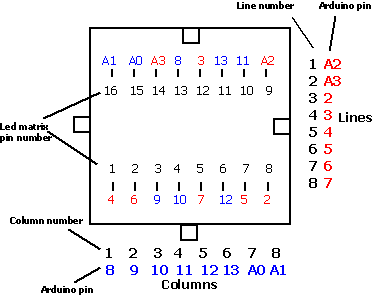
Led matrix vs. Arduino pins
Other version that works with WinAvr LedMatrixCompanion.c
Don't foget to create in the avrdude.conf a clone of the m88 named m88p that has signature signature = 0x1e 0x92 0x08; (see http://www.avrfreaks.net/index.php?name=PNphpBB2&file=viewtopic&p=564029)
LedMatrixCompanion.c
Akizukidenshi 32x16ドットLEDマトリックス表示装置パーツセット
Got that in a fukubukuro I can't remember when at 秋月電子, and decided to give it a try. Documentation is short, but module looks nice, chainable (if you had 2), etc... anyway they don't sell it anymore.Links
Code
void test3() {
  for (int y =0; y < 16; y++){

    for (int x =0; x < 16; x++) {
      if (x == y) {
        /*
          NEW LINE! This one kept me searching for a couple of evenings. The reason is that the SIN1 "new line" is not an active signal (like "go next line"),
          it's an information of which line to display. First time it's on the zero clock, then on clock 1, then clock 2, ... Once you understand that it's
          very logical in fact.
        */
        digitalWrite(PINSIN1, HIGH);
      }

      /*set leds*/
      if (x == b) {
        digitalWrite(PINSIN2, HIGH);
        digitalWrite(PINSIN3, HIGH);
      }
      delayMicroseconds (DELAYUS);

      /*read!*/
      digitalWrite(PINCLOCK, HIGH);
      delayMicroseconds (DELAYUS);

      /*go down      */
      digitalWrite(PINSIN2, LOW);
      digitalWrite(PINSIN3, LOW);
      digitalWrite(PINSIN1, LOW);

      digitalWrite(PINCLOCK, LOW);
    }

    digitalWrite(PINLATCH, LOW);
    delayMicroseconds (DELAYUS);
    digitalWrite(PINLATCH, HIGH);
    delayMicroseconds (DELAYUS);


  }

}
electrogeek.tokyo ~ Formerly known as Kalshagar.wikispaces.com and electrogeek.cc (AlanFromJapan [2009 - 2026])